
SmartLamp Controller Technical Details
This page is useful if you want to make changes or reprogram the SmartLamp Controller.
Return to Smart Lamp Controller main page.
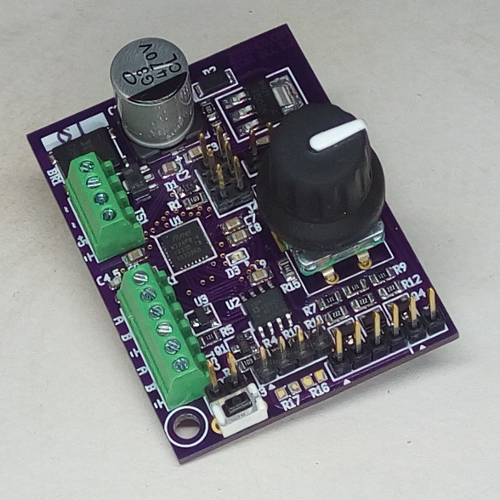
Wiring of the Smart Lamp Controller, showing the standard "Arduino digital pin numbers", named port, processor pin number and special features of those pins. For more information on the processor, the data sheet is available here
| SW# | HW Port | Pin # | Features | SLC |
|---|---|---|---|---|
| 0 | PD0 | 30 | RxD0 PWM | RS-485 |
| 1 | PD1 | 31 | TxD0 PWM | RS-485 |
| 2 | PD2 | 32 | PWM | knob button |
| 3 | PD3 | 1 | PWM | knob A |
| 4 | PD4 | 2 | knob B | |
| 5 | PD5 | 9 | PWM | Red |
| 6 | PD6 | 10 | PWM | Green |
| 7 | PD7 | 11 | ||
| 8 | PB0 | 12 | ||
| 9 | PB1 | 13 | PWM | Blue |
| 10 | PB2 | 14 | PWM | White |
| 11 | PB3 | 15 | MOSI0 TxD1 PWM | Ext PWM |
| 12 | PB4 | 16 | MISO0 RxD1 | |
| 13 | PB5 | 17 | SCK0 LED | |
| 23 | PE0 | 3 | SDA1 | Motion sensor |
| 24 | PE1 | 6 | SCL1 | Reverse Encoder option |
| PB6 | 7 | XTAL | ||
| PB7 | 8 | XTAL | ||
| PE2 | 19 | |||
| PE3 | 22 | MOSI1 | ||
| PC0 | 23 | MISO1 | ||
| PC1 | 24 | SCK1 | ||
| PC2 | 25 | |||
| PC3 | 26 | |||
| PC4 | 27 | SDA0 | ||
| PC5 | 28 | SCL0 | ||
| PC6 | 29 | Reset |
Motion Sensor Input
Older 'PIR' often require 12V. The rectified AC voltage (usually 12V) is available on the motion detector pin 4. The output of these sensors is often a contact to ground. The signal output of the sensor can be connected directly because a pull-up resistor is built into thet processor which is activated in the firmware. Extra pads are provided (marked R16 and R17) in case hardware pull-up or pull-down resistor are needed.
Be sure to use a PIR sensor that runs on low voltage, as are typically used with home alarm systems. PIR sensors used with outdoor floodlights run on high voltage house wiring, and should not be used.
Programming the SmartLamp Controller yourself
Many 'ISP' programmers are available at low cost (many under $20.00). Web search 'USBASP'. Some come with a 10 pin header, and these will require a 10 pin to 6 pin adapter, also commonly available. When using the Arduino IDE (integrated desktop environment), under the Tools menu, select 'No bootloader' and programmer 'USBAsp'.If you want to create your own software, or modify the built in software, the SmartLamp Controller can be programmed with the Arduino IDE. An In System Programmer (ISP) device is required such as the common USBISP and a cable with a 6 pin connector, typical of many Arduino compatible boards.. These low cost (as low as ) programming interface devices plug into your computers USB. Do a web search for "USBASP" to locate appropriate interface devices. Many of these devices have 10 pin connectors, and 10 to 6 pin adapters are available.
The included software compiles with the standard Arduino workstation system. A few extensions need to be installed.
PCB options
- All unused pins on the ATmega processor are terminated with solderable vias. This allows you to make connections to these pins for your own additions.
- To accommodate different types of sensors. For PIR (signal contact to ground)(add R16,18). For radar, only short R18 (series resistor or use small value since radar unit has series reistor already?)
- The encoder knob can be mounted on either side of the PCB. If it is mounted on the back, an additional status LED can be added by cutting the near by connection on the back side of the board. A minor code change is needed that will reverse the rotation direction.
Specifications
| SLC max Voltage Input | DC 31V, AC 22V |
| PWM Frequency | 500Hz by default |
These products are now sold as part of consulting projects only.
For information on obtaining products you can contact us here.
Return to Smart Lamp Controller main page.